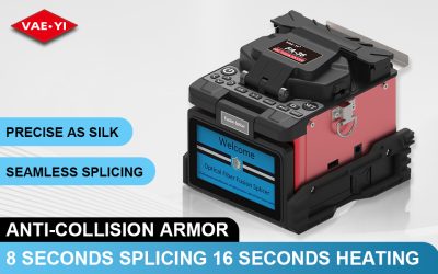
A fusion splicer takes two pieces of optical fiber, lines them up, and melts them together with an electric arc. The result is a single continuous strand of glass that carries light with almost no loss. So how does a fusion splicer work? The short answer: precision mechanics, high-voltage electrodes, and some clever optics. Nanjing Vaeyi Technology Co., Ltd. builds these machines for telecom crews, data center teams, and FTTH installers — so we’re going to break down the process the way we’d explain it to a new technician on site.
The Six Steps: From Stripped Fiber to Fused Joint
Every fusion splice follows the same sequence, whether you’re using a 4-motor FTTH splicer or a 6-motor core alignment machine. If you read our fiber splicing basics guide, you already know the concept — now here’s what happens inside the machine.
The six steps are:
- Strip — Remove the 250μm coating down to 125μm bare glass. Mechanical strippers like the VAEYI FSP-3 handle standard fibers. For specialty fibers with tough coatings, thermal strippers like the FSP-200PRO heat the coating to 50–180°C and peel it off cleanly.
- Clean — Wipe the bare fiber with alcohol-soaked lint-free wipes. A single dust particle on the end face can turn a 0.02 dB splice into a 0.3 dB mess. This step matters more than people think.
- Cleave — Score the fiber and snap it to create a flat end face. The cleave angle should be under 0.5°. The VAEYI P12 one-step cleaver averages ≤0.5° across 48,000 uses per blade position.
- Align — The splicer places both fibers in V-grooves and uses cameras to line them up. Core alignment and cladding alignment diverge at this step — more on that below.
- Arc discharge — The splicer fires a high-voltage electric arc between two electrodes. The arc melts the glass (around 2,000°C), and the fiber ends fuse together into one piece.
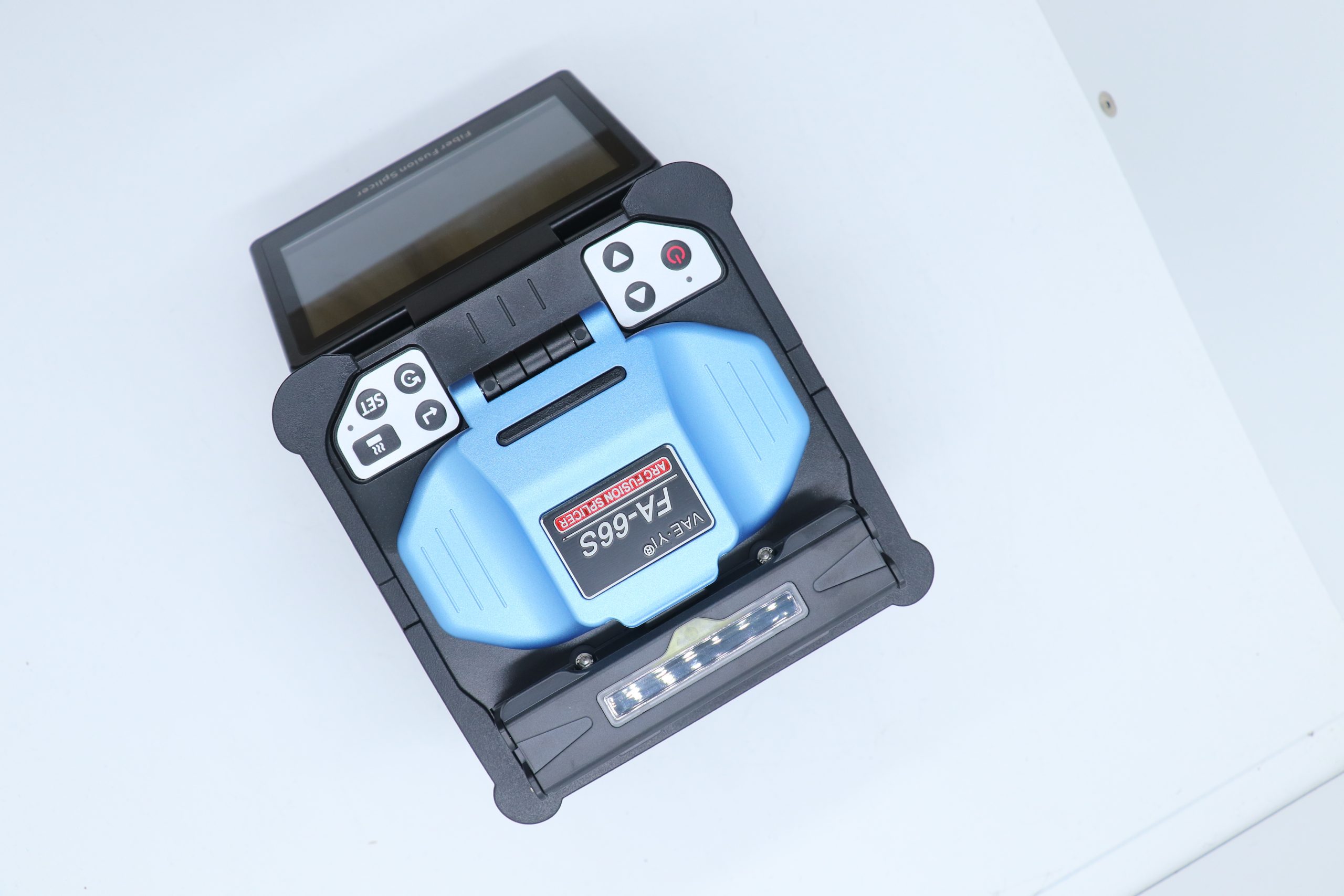
- Inspect — The splicer’s cameras check the splice for bubbles, misalignment, or deformation, then estimates the loss. On the VAEYI FA-66S, you can see the result at 380× magnification on the 5-inch screen.
On the FA-66S, the splice itself takes about 6 seconds in fast mode. Add 15 seconds for the heat-shrink sleeve, and you’re looking at roughly 21 seconds per splice end-to-end.
Core Alignment vs Cladding Alignment: What’s Actually Moving
Here’s something that confuses a lot of people. The fiber core — where the light travels — is only 9 micrometers across. The cladding around it is 125μm.
That’s a big difference.
A cladding alignment splicer lines up the outer cladding of both fibers and assumes the core is centered inside. It uses fewer motors (typically 4) and costs less. The FA-36, for example, uses 4 motors and cladding alignment, giving you 0.03 dB typical loss on single-mode fiber. It splices in about 8 seconds and runs on a 5200mAh battery good for roughly 250 splice-and-heat cycles per charge.
A core alignment splicer actually finds the core on each fiber and lines them up directly. It needs 6 motors, dual cameras, and more processing power. The FA-66S uses this approach and achieves 0.02 dB on single-mode fiber — 0.01 dB on multimode.
So why does core alignment cost more? Because it actually lines up the 9μm cores — not just the 125μm cladding. That means lower loss, fewer re-splices, and less wasted time on site.
If you’re doing FTTH drops where the link budget is forgiving, cladding alignment works fine. But if you’re splicing long-haul or data center links where every 0.01 dB adds up over hundreds of kilometers, core alignment pays for itself quickly.
The Electric Arc: How Heat Joins Glass
The arc is the heart of the fusion splicer. Two tungsten electrodes sit a few millimeters apart, and the splicer applies a high voltage between them. The air ionizes, current flows, and you get a plasma arc hot enough to melt silica glass.
The splicer controls three things during the arc:
- Arc current — typically 14–20 mA, adjusted for fiber type and environmental conditions
- Arc duration — about 2 seconds for the main fusion, with a brief pre-fuse to clean the fiber ends
- Feed speed — the fibers are pushed together at a controlled rate during the arc
Here’s what happens to the glass: the fiber ends soften, surface tension pulls them into a smooth taper, and as they’re pushed together, the glass merges. Done right, there’s no visible boundary — just one continuous piece of silica.
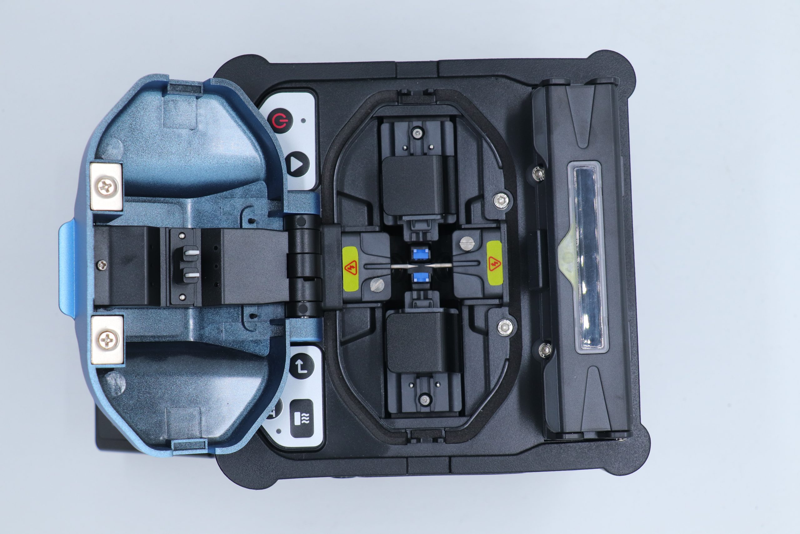
Most modern splicers also run a cleave angle check and gap set before firing the arc. If the cleave angle is too large, the splicer refuses to fire and tells you to re-cleave. We’ve found that catching bad cleaves before the arc saves a lot of wasted electrodes — and electrodes aren’t free.
Splice Loss: Where Does 0.02 dB Come From?
Splice loss is the number that matters. A typical single-mode fusion splice should come in at 0.02 dB or less. But what actually causes that loss?
Six main factors:
- Lateral offset — the cores aren’t perfectly aligned laterally
- Angular misalignment — the fibers aren’t straight relative to each other
- End face quality — a bad cleave means uneven surfaces that don’t fuse cleanly
- Contamination — dust or residue on the fiber end
- Arc parameters — too much heat causes bubbles, too little causes incomplete fusion
- Fiber type mismatch — splicing different fiber types (like G.652 to G.657) adds loss
The splicer estimates loss by analyzing the splice image — it looks for taper shape, core continuity, and visible defects. For core alignment splicers like the FA-66S, this estimate is typically accurate to about ±0.01 dB.
For the most accurate measurement, you’d use an OTDR to test the splice from both directions and average the results. But for day-to-day field work, the splicer’s built-in estimate is usually good enough to decide whether to accept or re-splice.
If your splicer keeps reporting losses above 0.05 dB, don’t blame the machine. Check your cleaver blade, clean your fibers better, and make sure you’re not working in a dusty environment.
Want to know whether the FA-66S core alignment splicer or the FA-36 FTTH splicer fits your workflow? Send us a message — we usually reply within a few hours.